Saturday, February 20, 2021

ROS adventures

 At first when I tried to install ROS I was very confused, because I was under the impression that the Raspberry pi was a very unique platform that needs it's own approach. So far I used Raspian Buster on it.

This led to a lot of confusion with me trying to install old ROS distributions such as Kinetic and Melodic. Because those are the only ones that Raspberry pi tutorials are made for. On the ROS wiki the distributions are said to support a limited number of architectures and operating systems. When I looked up what architecture the Raspberry pi has I got this result:


aarch

Which didn't seem to be listed. However it turns out that it is the same as arm64 architecture! This was a huge break through, because it meant that I could use any operating system as long as it had an arm64 port. I picked ubuntu, because it would allow me to run the latest ROS distro as of Febuary 2021 which is Noetic Ninjemys. 

As a side note noetic means relating to intellect or mental activity, and ninjemys is an ancient turtle species that is  literally translated to ninja turtle. Pretty neat!

I chose to install ubuntu 20.04 LTS server, because I'm mostly going to work with the command line. Hopefully I don't regret this decision, but if I do I can always install some more GUI stuff on it. This install was pretty challenging, because I wanted to do it headless. Meaning I didn't have a monitor setup, so I couldn't verify what was going on at first. I wanted to edit the network-config file on the SD card of the raspberry pi and enable ssh on it, so when I turned it on it would be ready to do and I could ssh into it. This proved difficult however as the wifi adapter refused to turn on. After a lot of failed attempts I gave up and plugged in my monitor. 

It turns out I forgot a quotation mark, which was messing up the network-config file. This surprisingly didn't let me log in to the pi at all. After I fixed it, it still wouldn't log into the Wi-Fi however. To solve that I edited the netplan YAML file on the ubuntu server after logging into it with a monitor and keyboard. 

This YAML file was terrible as it was super finicky with indentation. What I discovered is that each indentation had to be 3 spaces per seniority level. So something like this.

human:

   engineer:

      peter:

After I fixed this the netplan finally was able to be generated and applied. After that I ran

sudo apt update

sudo apt full-upgrade

sudo reboot

And finally for the first time it booted up with Wi-Fi! I was very happy, now I was able to ssh into the robot from anywhere in the house.

Then I was able to easily install ROS following this tutorial:

http://wiki.ros.org/noetic/Installation/Ubuntu

This is a huge breakthrough as I'm finally getting to the part that I want to do, the robot programming. ROS is  a very valuable skill to have in the robotics industry and my hope is that I can make myself more employable through this practice. The next step is to figure out serial communication via ROS and try to set up some nodes.

Monday, February 15, 2021

Improving the wire mess

 Today I also started the task of improving the wiring situation. Currently there are way too many wires and the thing looks ugly as sin. I managed to find an old yogurt container that fit the dimensions of the robot nicely. I decided to move the arduino and the raspberry pi to the top, because those are the components that I interact the most, and hide the ugly motor controller mess under the contrainer. I also made a small plow that can be used for moving objects and a little front face to mount the ultra sound sensor and the camera.


 One problem that I have yet to solve is the battery placement. I want it to be removable, but I also want it to be secure. It is by far the heaviest part of the circuit and I don't want it to fall off when the robot accelerates quickly. 

So far I have it taped onto the back of the robot. But one new improvement is that I have added a power switch! This make the whole thing a lot safer now.

Encoders

 If I hope to be able to locate my robot, I need some sort of sensor, for it to know where it is. When I bought the chassis I decided to get something with encoders. 

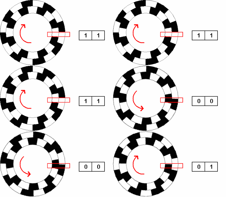
Magnetic encoders work by sensing a change in magnetic field as a disk attached to the motor rotates. The type that I have is called a 2 phase encoder. 


 One ring represents signal A and the other represents signal B. Based on the positions of the rings the logic of the signals will tell me if my robot's wheels are going backward or forward.

The problem is that I have 4 motors, and each of them has an encoder. I am already using 3 wires per motor, just to drive them. And with the encoders I will need another 2 wires per motor. 

I can use the analog pins as digital inputs, but I am still a bit short. My hope was to use pins 0 and 1, but they are ties to the serial communications. So basically I can either talk to my raspberry pi or I can have these two pins. Great... 

Since I don't want to buy another bigger arduino, I found another solution. I can use a shift register! This device would allow me to power 8 pins as digital output, while only using 3 on my arduino. Luckily I have a 74HC595 chip laying around.

The pins that are driven by the shift register will technically react slower, but the delay is so small that it shouldn't be noticeable.

So next time I will need to figure out how to use that, put some of the motor pins on there, and plug the encoder into the digital pins that are now available.

Other than this minor hickup, I have gotten all of the encoders to report data. This is amazing news. With this done, I can start getting into ROS more and using the data from the encoders to control the robot.

Speaking of which, I have managed to get basic serial communication to happen between the raspberry pi and the arduino, I wrote a simple script, where the arduino spits out the position of the wheel and the raspberry pi can read it. Currently I am controlling the raspberry by via ssh, so I can read the output on my nice computer screen.

Wednesday, February 3, 2021

Motor control success

 Hooray! I got the motors to work!


So previously I was having a lot of trouble with the raspberry pi to achieve consistent motor control. I decided to try an arduino, the hope was that I could get away with an arduino nano, however it's votage of 3.3 was not enough to drive the 5V motor controller. Since then I switched to an arduino Uno.


At first I was having a lot of trouble with the motors turning on and spinning in the right direction. Then I moved the line that activates pwm outside of the loop that controls individual wheels. This helped the timing a lot and I will use this method going forward. Presumably I won't need to have the wheels at different speeds.

Here is a video of the robot performing a test routine:


The robot performs considerably better on linoleum than on carpet. This is actually a bit of a problem, since if I want it to drive around the entire house, it will either need to be able to :

1. Detect carpet

or

2. Be able to know which parts of the house have carpet, and be able to accurate find its own position from encoder feedback. I think this will be very unreliable.

The next steps will be to implement communication between the arduino and  the raspberry pi. In another project I found done by masters students at EPLF, they used I2C to setup a master-slave system, with the Arduino being in control. The idea here is that the arduino is bullet proof and will execute commands even if the pi fails. Since I've already spent a considerable amount of money on this thing I won't implement this as I would need to buy and I2C bus. Instead I plan to use serial communication by connecting the two platforms with a usb cable. I'm running out of space on the chassis and might need to start elevating components for this to work.

One of my problems during the motor control tests is that one motor kept turning. Later I figured out that this is because the digital pin 1 (which is also the tx pin) kept out putting signals. If the arduino is going to be my main platform that takes in sensor input, then I'm going to use so many pins that I will inevitable need digital pin 1. So I will need to figure out how to configure it. 


That being said I can still start on connecting the encoders. Each encoder has a 5V and ground pin and an A and B output. the A and B are signals that will help determine the amount of rotations the wheel makes. More on this in a future post.

Also I finally recieved my rechargeable batteries. So now I can switched to a more sustainable power source. This will drop the votage of my system considerable but I think it should still function. The demo above used half speed and was still decently fast.

Thursday, January 28, 2021

Cleaning up the wires and experimenting with motion.

Alright so today, I installed the boards on the chassis using screws. I had to drill the chassis and now it looks much better with everything mounted. While I am troubleshooting the motion of the robot I took off the camera and the distance sensor. The battery packs are currently, hot glued onto the chassis, until I figure out something better. I didn't have enough screws, so each board is mounted with only two in diagonal corners.

 The super long motor cables are very annoying, but I don't want to cut them as I'm nervous about soldering them. Maybe I can zip tie them?

Currenltly I am working on motor control. I am using a raspberry pi and two L298n motor controllers.So far I am having trouble getting a consistent response and I suspect the GPIO pins on the pi. The creator of the Rpi.GPIO library mentioned that it is not suitable for real time applications, since python does some stuff in the background that messes up the timing.


As an option I am considering adding an Arduino to the project, to improve the robot's real time response. Eventually I want to be able for the robot to drive autonomously and it will be very difficult in that case to compensate for delays.

Also another thing that I have discovered is that pins 0-8 on the Raspberry pi start out as HIGH. Which is terrible, because it means if I am using them to control the robot, it will be spinning wheels while the program isn't running.

In the picture above I have an arduino nano clone inserted onto the bread board. I wonder if that will be enough to deal with the motor controller issue. If that doesn't work I can switch to an arduino uno I have lying around. But of course I need to think about how I am going to power it. They can be powered with a 9V battery, but I wonder if that will run out too fast.

Electrical components of the robot.


The goal of this exercise is to create an autonomous mobile robot that can drive around my house and maybe even perform a task such as pushing balls. In order to do the advanced computation required I'm going to use a Raspberry Pi 3 A. This little computer should be enough to take in data from the sensors (camera, ultrasound) and output the signals to drive the motors. 

The raspberry pi runs on 5 volts, but the motors require 12V. Furthermore the pi can not supply enough current. To solve this issue I am going to use the L298N motor controllers. These are fairly popular in the hobbyist community and can handle my voltage. They are also capable of PWM (Pulse width modulation), which is used to control speed of the motors.

In order to drive 4 motors I am going to use 2 of these controllers since each of them has 2 outputs. And to power the motors, I am going to use a simple battery holder that can house 8 AA batteries. When using non-rechargable batteries of 1.5V each I will be able to get 8*1.5=12V that I require. This is purely because I am being cheap and do not want to shell out for a bulky LiPo battery that is used to power drones, and RC cars. Eventually I can switch to rechargeable batteries. Those have the voltage of 1.2 volts, which will get me about 9.6V, this the robot is just used to drive around my house this will be fine as I don't need it to go as fast as it can.

The raspberry pi is powered by it's own stand alone battery, which is essentially a phone charger. But Peter, why can't you just use the main battery pack to power the pi??? I'm glad you asked. The reason for that is that the pi needs a specific voltage and current, which I can not accurately produce with the main battery. I have tried using a populu voltage regulator to step down the battery voltage to 5V, but it wasn't consistent enough power the pi.

I was really excited to get started with this project, so as soon as I put the chassis together with screws I slapped on all the electronics with tape and tested it.


 As you can see this is a huge mess. One of my favorite robot philosophies is BEAM. Which stands for Biology, electronics, aesthetics, mechanics. The idea behind BEAM is to build simple robots based on simple organisms such as instincts. As such just like insects these robots do not have a brain. Meaning the don't use micro-controllers, but instead use analog circuits to control the robots. This is very different from what I am doing, but the philosophy of aesthetics applies all the same. Aesthetics are important, because often times they are directly related to safety and overall sense of the concept. If a gazelle had its guts hanging out it would be pretty ugly right? Yeah! It's the same with the robots. Having a bunch of wires everywhere looks pretty gross and is not very safe.In the future I will install the board with screws onto the board. I also need to figure out how to mount the camera and the ultra sound sensor that will be used to measure distance.

But for the time being I can test this thing. Using a simple python script and the Rp.GPIO library I was able to test the motors. And the results were not great. Each motor spins backwards and forwards, but when I try to spin them together, they aren't synced up. Sometimes some of them don't turn on. I'm happy that all of them spin, but I need to work on making them more consistent.

Mechanical parts of my new robot project.


In order to keep myself busy and my skills sharp. I have decided to make an autonomous mobile robot. I wanted a sturdy chassis that could house many different components and support a fair bit of weight. I also wanted to have encoders so I could build closed loop control. And my most coveted feature is mecanum wheels.


For those of you that are not aware mecanum wheels have rollers that allow spin, thus eliminating the force of friction in one direction.

By Gwpcmu - Own work, CC BY 3.0, https://commons.wikimedia.org/w/index.php?curid=11440618

Because the rollers allow spin, if this wheel is turned forward it would actually travel diagonally, since the only grip it has is diagonal. By arranging four of these wheels together we are able to balance the friction forces and do some crazy stuff.


As the picture above shows a robot with four mecanum wheels can travel in any direction, including sideways and diagonally. Needless to say I am very excited to try them out. 

So to accomplish all of this I bought the moebius robot chassis from moebius tech in china. The cost was about 115$ CAD, which is reasonable in my opinion. Here is a picture of the components, prior to assembly.


The kit is meant to go with the solution that the company provides, meaning you're meant to follow their instructions exactly and install an Arduino on there. This is why you see a very specific pattern of holes on the chassis. They are meant to mount the electrical components that the company provides. We are gonna go off the beaten path and install different components, so hopefully at least some of those holes will line up with the mounting holes of my electronics.

Part of my decision to buy this also comes from the material of the chassis. Aluminum is an amazing material to work with since it is light, easy to machine and doesn't rust. My chassis is anodized to be a stylish black, which I'm very happy with. If I need to add more hardware onto it in the future such as a robot arm, it will be strong enough to support the weight and also to attach securely.


NEW Project Autonomous underwater vehicle!

  I have been more and more interested in Autonomous Underwater Vehicles and ocean exploration. I live on the coast with direct access to th...